55-22-02
ERCO
Applies to 415-C, -CD and -D Aircraft Serial Numbers 113 Through 2468 for Fuselage Tank Replacement;
Serial Numbers 113 Through 2622 For Wing Tank Replacements.
Compliance: Inspection required each 25 hours; replacement at time leakage discovered.
Unless the terneplate fuselage fuel tank has been replaced with a stainless steel tank and the terneplate
wing fuel tanks replaced with aluminum alloy or stainless steel tanks, the tanks should be inspected
frequently for signs of leakage at intervals not greater than 25 hours. If tank leakage is observed, the tank
should be replaced with one of stainless steel or aluminum alloy, as required, before the next flight.
Erco Service Department Bulletin No. 10 and No. 10A and Memorandum
No. 31 and Memorandum No. 43
pertain to the inspection and replacement of these tanks.
This supersedes AD 47-50-10.
Service Bulletin SB-10
Model: A2
Serials: A-2 and on
Subject: More frequent inspection of fuselage fuel tank.
From the interior of the aircraft, frequently check for leakage or seepage of the fuselage fuel tank. Check all
plumbing connections for proper tightness and weld seams of the tank for possible cracks. Presence of red
staining will indicate a leak or seepage exists and will indicate its point of origin.
Over-filling of the tank may also cause red staining. A thorough check should be made to determine the
origin of a leak or seepage.
Any leak should be corrected before operating the aircraft.
Service Memorandum No.31
SUBJECT: Fuel System Operation
1. The fuel system in the Ercoupe was designed to incorporate simplicity and safety in operation, however,
due to unforeseen operational difficulties and failures which have occurred in the field, it has now been
deemed necessary to redesign certain parts of the system. The basic operation has, however, remained
unchanged. In order that there is a complete understanding of changes, operation and maintenance of the
fuel system, the following discussion is supplied,
2. The fuel system is entirely automatic as long as the fuel pump is operating. In the event of a fuel pump
failure, there is no fuel being transferred from the wing tanks to the fuselage tank. After such a failure, the fuel
available for continued engine operation is limited to the capacity of the fuselage tank.
3. Subsequent to Serial Number 2623, fuselage and wing gas tanks constructed of aluminum have been
employed in the Ercoupe. This change was made to improve the quality of the tanks, render more
satisfactory service, and to save weight. A description of both the template tank and the aluminum, will be
discussed in this memorandum. They will be referred to as a "template tank" and "aluminum tank," as the
case may be, even though template tanks have been superseded by stainless steel for replacement
purposes.
Wing Tanks:
4. The capacity of either type wing tank is nine (9) gallons of fuel. The two sides are inter-connected with
aluminum tubing. The fuel pump transfer suction line is connected to that inter-connection with a "tee" fitting.
A shut-off valve is provided in the pump suction line above this tee. This valve and tee are located in front of
the right hand seat, near the floor. It should be kept in the open position, except for emergencies such as line
failure.
5. Tanks fabricated of stainless steel are being shipped on parts orders in lieu of the template tanks. The
stainless steel tanks are interchangeable with the template tanks. All Ercoupes Serial Numbers 813 to 2622
inclusive, can be altered by certain modifications to take aluminum wing tanks. This installation will be
described in detail, in a separate publication.
6. The fuel quantity gauge on the template tank installations is located in the right wing tank and it consists of
a float type indicator, encased in a plastic tube. It is marked full, half full, and empty. This gage may give
false readings due to improper venting, chiefly the error is reading half full in flight when more than half full of
gas. This can be remedied on Ercoupes Serial Numbers 513 to 2623, by complying with the following
procedure:
Affected part--415-48089--Vent Assembly
1. Remove 6 x 32 screw and nut which attaches vent to the right side of the fuselage.
2. Break the vent loose from the gage tube by turning the vent.
3. Realign the vent, by lowering the forward end, until it lies in a position from 40° to 45° with
relation to the external longeron.
4. Drill a No. 28 hole through the fuselage skin, using the vent plate as a guide.
5. Insert the same 6 x 32 screw that was removed in operation No. 1.
6. Reseal vent to plastic gage tube by using clear nitrate dope, or any suitable cellulose cement
(See illustration No. 1.)
7. Close the original hole with a rivet.
The vent tube (part No. 415-48089) may be installed on Ercoupes prior to Serial Number 513. The
following procedure may be used to make the installation:
1. Mark hole center on fuselage skin and wing tank gage tube.
a. Locate vertical center line of gage tube. Transfer center line to fuselage skin.
b. Draw line 1/4" below the top of the gage tube. Transfer it to the fuselage skin.
2. Remove gage from the right wing tank.
3. Drill hole (No. 12 drill) in the fuselage skin at point located in operation No. 1.
4. Drill hole (No. 12 drill) in the gage tube, 1/4" below top.
5. Replace gage tube on tank.
6. Insert vent through outside of ship and follow directions 3, 4, 5, and 6 of the procedure used for
aligning the vent.
7. The fuel quantity gage in the aluminum wing tank is different from the one used in the template tank. The
new gage is mechanical and is operated by a float resting on the surface of the fuel, which moves a marked
dial, showing the amount of fuel in the tank. This gage is located in the left wing tank where it extends into the
cabin forward of the seat.
8. Reports from the field state that these gages can become inoperative due to the rusting of the working
parts in the gage. It is recommended that all of the new type fuel gages be periodically inspected and if, after
such inspection, the gage is found to be rusted, it should be replaced or repaired. If the latter procedure is
desirable, the following information is supplied to aid in making repairs.
1. Remove the gage from the tank, which gage is held in place by 12 screws, (AN 520-4-6).
2. Disassemble the gage and remove all of the rust from the affected parts.
3. Paint these parts with zinc chromate or spar varnish, and allow paint to dry thoroughly.
4. Reassemble the gage.
5. Prior to replacing the gage in the tank, remove all traces of the original sealer, (EC-570,
product of the Minn. Mining and Mfg. Corp.) from the parting surfaces of the gage and the tank.
If the original material used for a sealer is not available, Permatex or similar gasket cement
may be used.
6. Replace the gage, using some of the sealing cement to secure screws.
9. It has been the experience of some Ercoupe owners and operators that line mechanics put the wing tank
caps on backwards. To prevent malfunctioning of the fuel system, it is imperative that the caps be put on the
tanks with the vent hole to the front. This provides venting of each wing tank and will prevent syphoning or
unequal flow of the fuel. Unequal flow may result in the fuel pump being unable to transfer all of the fuel from
the wing tanks to the fuselage tank.
10. It is recommended that the wing tank cap be marked in a manner to indicate proper positioning. A
painted red line on the wing behind the cap to match a painted sector on the cap should be used. The
painted sector on the cap should extend from the point of engagement to the locked position, as indicated
on accompanying sketch No. 2.
11. On Ercoupes subsequent to Serial Number 2623, the filler neck and cap combination is foolproof and
the caps cannot be put on backwards.
12. The sealing of the cap gasket also affects proper venting. If difficulty is experienced in attaining a good
seal of the gas cap, which is an unmachined casting, the sealing surface may be filed smooth and the
gasket cemented to this surface. Should there be an excessive amount of solder on the filler neck sealing
surface, it may also be removed by filing.
13. A more suitable gasket, made from a synthetic rubber "Neoprene" (sponge rubber) will be available
soon. The oil sump gage gasket (Continental Motors Corp. Part No. 22404) has also been found to provide
a satisfactory substitute for our gas tank cap seal.
14. The capacity of the template fuselage tank is five gallons; the aluminum fuselage tank will hold six
gallons of fuel. The fuselage template and aluminum tanks are not interchangeable. However, stainless steel
tanks can be installed in place of the template fuselage tanks, without modification, and should be so used.
(See Service Policy Letter A-4).
15. The line that feeds fuel, by gravity, from the fuselage tank to the carburetor is connected to the fuselage
ttank through a shut-off valve and tank finger strainer. This valve on the template tank has a position selector
on the instrument panel, whereas the valve on the aluminum tank may be turned on or off by reaching under
the left side of the instrument panel. This valve is for emergency purposes and should not be used to shut off
the engine.
FUEL PUMP, FILTER, AND PLUMBING:
16. The fuel in the wing tanks is transferred to the fuselage tank by a fuel pump that is mounted on the
engine. A restricted fitting is located on the outlet side of the fuel pump, and limits the output of fuel to a
quantity slightly in excess of the requirements of full throttle operation.
17. A return, or overflow line is provided in the fuselage tank. This line will return to the wing tanks any fuel
that is pumped into the fuselage tank in excess of its capacity. Excess fuel is returned to the right wing tank
with the template fuselage tank and to the left wing tank with the aluminum fuselage tank.
18. A sediment bowl type filter is located in the gravity fuel feed line. Its function is to accumulate any water
or foreign matter that might otherwise enter the carburetor. The bowl is detachable for cleaning. This should
be included on the daily inspection sheet. The bowl should be safetied after cleaning.
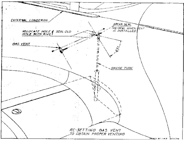
FIG. 1
RE-SETTING GAS VENT TO OBTAIN PROPER VENTING
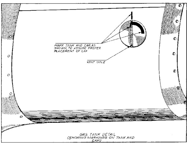
FIG. 2
GAS TANK DETAIL (SHOWING MARKINGS ON TANK AND CAP)
Service memorandum No.43
SUBJECT: Modification of Aluminum Tanks and Fuel System Lines
(Effective on Ercoupe Serial Numbers 2623 to 3467, incl.)
1. There have been two minor modifications in the tanks and fuel system lines since the change from
Template to Aluminum gasoline tanks, which occurred on Ercoupe Serial No. 2623. The first fuel system
was installed in Ercoupes No. 2623 to No. 3220, inclusive. The intermediate system was installed in
Ercoupes No. 3221 to No. 3467, incl. The improved system now in use was installed in Ercoupes No. 3468
and subsequent. Since the tanks and lines used in the latest system will be the only replacements available,
it is desirable to modernize the other two systems when any major replacements are required. This will
provide the best fuel system and eliminates the necessity of carrying large varieties of parts. However, the
procedure for using a stock tank by installation of special lines and reducers is given below for those who do
not desire to make a complete change.
2. While complying with this memorandum, use Parker Sealube (6PE), or its equivalent, on all fittings; do
not tighten fittings until all lines have been installed. Tape and shellac lines at any point where they may rub.
The right wing tank does not have to be modified in any way. The "Shut-off Valve to Firewall Tube
Assembly" (carburetor supply) (415-48166) is interchangeable with "Tube Assembly" 415-48163. If it is
necessary to replace the old Tube Assembly, order "Shut-off Valve to Firewall Tube Assembly"
(415-48166), two washers (AN960-A916L) and nut (AN924-6D).
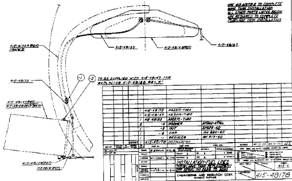
1. Modification of the First System: (Ref. Page 3, Fig. 1 )
(Serial Nos. 2623 to 3220, incl.)
a. If only the improved "Fuselage Tank" (415-48145) is to be used, install this tank, and install
replacement lines as follows: (Refer. ERCO Drawing 415-48178 ).
(1) Connect "Fuselage Tank to Reducer Tube Assy." (overflow) (415-48133) to fuselage tank,
left hand rear fitting.
(2) Attach Reducer (AN919-6D) to this line.
(3) Connect "Reducer to Bulkhead Elbow Service Tube Assy." (415-48175) to above reducer
and original bulkhead elbow (AN833-4D) at Frame "B".
(4) Attach "Fuselage Tank to Firewall Tube Assembly" (pump pressure) (415-48167) to
fuselage tank, right hand rear fitting, and assemble to firewall and make secure with nut
(AN924-4D).
(5) Tighten all fittings securely.
(6) Reconnect hoses on forward side of firewall.
b. If only the improved "Left Wing Tank" (415-48147L) is to be used, install this tank and complete
modification as follows: (Ref. ERCO Drawing 415-48178 ).
(1) Install Cap (AN820-6D) on 1eft wing tank overflow fitting to close off the unused hole.
c. If both the improved "Fuselage Tank" (415-48145) and the improved "Left Wing Tank"
(415-48147L) are to be used, install these tanks, and install replacement lines as follows: (Ref.
Page 5, Fig. 3. )
(1) Connect "Fuselage Tank to Union Tube Assembly" (overflow) (415-48133) to back of
fuselage tank, left hand fitting.
(2) Attach Union (AN815-6D) to this line.
(3) Drill or cut a 27/32" diameter hole in Frame "B", 5" above the left longitudinal (415-31007).
This hole should be in the center of this section.
(4) Connect "Union to Left Wing Tank Tube Assembly" (overflow) (415-48134) after passing
line through new hole. Install elastic grommet (AN931-8-13) in the hole.
(5) Connect interconnecting tube (415-48109) to new left tank and install cap (AN820-4D) on
tee after removing old overflow line.
(6) Connect "Fuselage Tank to Firewall Tube Assy." (Pump pressure) (415-48167) to
fuselage tank on right hand rear fitting, and assemble to firewall using washer
(AN960-A716L) on each side of firewall and make secure with nut (AN924-4D).
(7) Tighten all fuel system fittings securely.
(8) Reconnect hose at forward side of firewall.
(9) To keep the left map compartment assembly from touching the overflow line, fasten Map
Compartment Mounting Clip (415-53209) to the third screw forward of Frame "C" in the
upper side of the left fillet. Attach map compartment assembly to clip with Sheet Metal
Round Head Screw (AN530-4-6).
2. Modification of Intermediate System: (Ref. Page 4, Fig. 2. ) (Serial Nos. 3221 to 3647, incl.)
a. If only the improved "Fuselage Tank" (415-48145) is to be used, install this tank, and install
replacement lines as follows: (Ref. ERCO Drawing 415-48179 ):
(1) Connect "Fuselage Tank to Reducer Tube Assy." (overflow) (415-48133) to back of
fuselage tank, left hand fitting.
(2) Attach Reducer (AN919-6D) to this line.
(3) Connect "Reducer to Left Wing Tank Service Tube Assy." (overflow) (415-48176), after
passing line through hole in Frame "B".
(4) Connect "Fuselage Tank to Firewall Tube Assy." (pump pressure) (415-48167), to
fuselage tank and assemble to firewall using washer (AN 960-A716L) on each side of
firewall and make secure with nut (AN924-4D).
(5) Tighten all fuel system fittings securely.
(6) Reconnect hose to forward side of firewall.
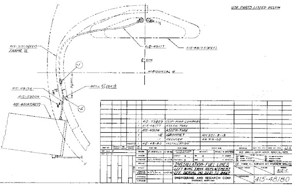
b. If only the improved "Left Wing Tank" (415-48147L) is to be used, install this tank, and install
replacement lines as follows: (Ref. ERCO Drawing 415-48180 ).
(1) Connect "Fuselage Tank to Reducer Service Tube Assy." (overflow) (415-48177) to
fuselage tank.
(2) Attach reducer (AN919-6D) to this line.
(3) Drill or cut a 27/32" diameter hole in Frame "B" 5" above the left longitudinal (415-31007).
This hole should be in the center of this section.
(4) Connect "Reducer to Left Wing Tank Tube Assy." (overflow) (415-48134), after passing
line through new hole. Install elastic grommet (AN931-8-13) in the hole.
(5) Connect interconnecting tube to new tank.
(6) Tighten all fuel system fittings securely.
(7) To keep the left map compartment assembly from touching the overflow line, fasten Clip
(415-53209) to the third screw forward of Frame "C" in the upper side of the left fillet.
Attach map compartment assembly to clip with Sheet Metal Screw (AN530-4-6).
c. If both the improved "Fuselage Tank" (415-48145) and the improved "Left Wing Tank"
(415-48147L) are to be used, install these tanks, and install replacement lines as follows: (Ref.
Page 5, Fig. 3 ).
(1) Connect "Fuselage Tank to Union Tube Assy." (overflow) (415-48133) to back of fuselage
tank, left hand fitting.
(2) Attach Union (AN8l5-6D) to this line.
(3) Drill or cut a 27/32" diameter hole in Frame "B", 5" above the left longitudinal (415-31007).
This hole should be in the center of this section.
(4) Connect "Union to Left Wing Tank Tube Assy." (overflow) (415-48134), after passing line
through new hole. Install elastic grommet (AN931-8-13) in the hole.
(5) Connect "Fuselage Tank to Firewall Tube Assy." (pump pressure) (415-48167) to fuselage
tank and assemble to firewall, using washer (AN960-A716L) on each side of firewall and
make secure with nut (AN924-4D).
(6) Connect interconnecting tube to new wing tank.
(7) Tighten all fuel line fittings securely.
(8) Reconnect hose on forward side of firewall.
(9) To keep the left map compartment assembly from touching the overflow line, fasten clip
(415-53209) to the third screw forward of Frame "C" in the upper side of the left fillet.
Attach map compartment assembly to clip with sheet metal screw (AN530-4-6).
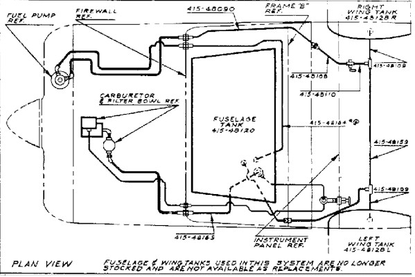
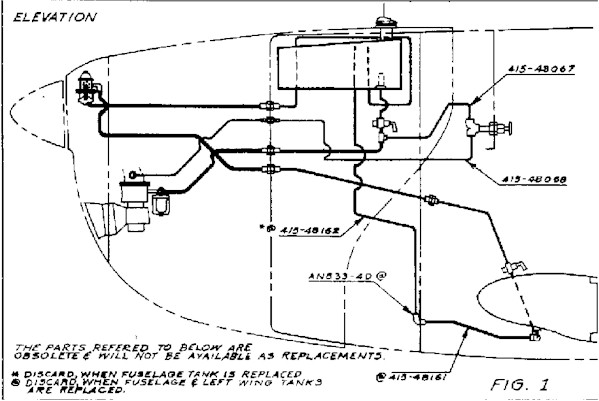
FIG. 1
FIRST SYSTEM-ERCOUPES 2639 TO 3220, INCL.
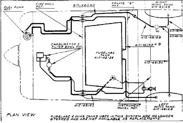
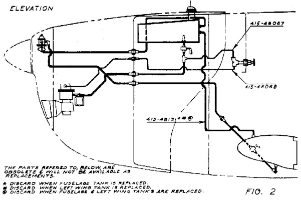
FIG. 2
INTERMEDIATE SYSTEM-ERCOUPES 3221 TO 3467, INCL.
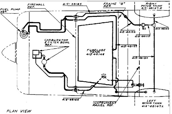
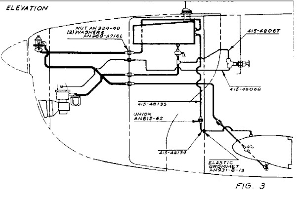
FIG. 3
IMPROVED SYSTEM-ERCOUPES 3468 & SUBSEQUENT
DRAWING 415-48179
INSTALLATION-FUEL LINES FUSELAGE TANK REPLACEMENT
EFF. SERIAL NO. 3221 TO 3467
DRAWING 415-48180
INSTALLATION-FUEL LINES LEFT WING TANK REPLACEMENT
EFF. SERIAL NO. 3221 TO 3467
Return