47-20-08
ERCO
(Was Mandatory Note 16 of AD-718-6.)
Applies to 415-C, -CD and -D Aircraft.
Compliance required prior to July 1, 1947.
(a) Install a new battery box drain tube to extend at least 1/2 inch below the fuselage belly skin if this
has not been already incorporated in the airplane.
(b) Examine the fuselage structure and controls carefully for corrosion. If corrosion is found on the
structure, the affected areas should be washed with an alkaline solution and followed by a thorough
clear water rinse. Corroded controls should be replaced.
(c) Examine the baggage compartment for deterioration. If damage is evident, wash the affected
area with a diluted alkaline solution and rinse with clear water. Reinforce any damaged areas with
10 1/2-ounce single filled water-resistant canvas, double sewn with 16-4 glace finished thread.
(d) Install decalcomania (Erco P/N 415-54062) on the top of the battery box cover.
(Ercoupe Service Department Memorandum No. 44 dated February 17, 1947, and Ercoupe Service
Department Bulletins No. 8 dated May 24, 1946, and
No. 22, dated February 3, 1947, also cover the above
subjects.)
Service Bulletin SB-8
(4-21-66)
Model: A2
Serials: A-2 through A-144
Subject: Wing Fuel Tank Filler Cap Rework
The following rework may be accomplished to eliminate the possibility of fuel overflow and in-flight
siphoning: (Refer to Figure 1 )
(1) Drill # 30 (.128) diameter hole through center of filler cap.
(2) Install AN380C3-8 cotter pin downward through hole in filler cap.
(3) Install 224 tube cap with open end against filler cap and cotter pin extended through the hole in
the opposite end.
(4) Install AN960C6 washer and bend tabs of the cotter pin flatly against washer and bottom of
cap.
The above parts (1 each 224 tube cap, AN380C3-8 cotter pin, and AN960C6 washer) will be shipped,
prepaid, upon request.
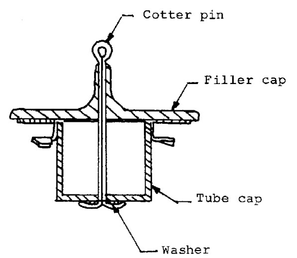
Figure 1.
Service Bulletin No.22
SUBJECT: Battery Box --Modification of
Electrolyte leaking from the battery box will cause corrosion of structural members of the aircraft and
deterioration of the baggage compartment. This can occur only when acid is spilled from the battery due to
improper servicing of the battery. Proper battery servicing and electrical system checks are described in
Service Department Information Memorandum No. 23 and No.
44.
This bulletin is prepared to provide instructions for modifying the battery box. Two modifications are
described. Part A provides for the addition of a decalcomania on the battery box cover carrying a set of
instructions for servicing the battery. Part B provides for the addition of an extension plate to the battery box.
This extension, when completed, will reduce the possibility of acid entering the fuselage structure if spilled
within the box.
PART A
This modification is considered necessary in view of the excessive number of reports concerning improper
battery servicing. To that end the material required will be supplied to Ercoupe Distributors and Dealers on a
no charge basis. Instructions for the installation are as follows:
1.Modification of Battery Box Cover:
a. Modify battery box cover as follows:
(1) Remove battery box cover.
(2) Remove the existing placard and clean the upper surface of the cover. Use dope thinner to
loosen the cellulose tape.
(3) Install the Decalcomania (415-54062), centered, on the top of the cover.
(4) Apply one coat of clear lacquer over the newly installed decalcomania.
PART B
This modification is presented for those who desire to add it to their Ercoupe. It may protect the interior of
the airplane from corrosion by battery acid spilled during careless or improper battery service. The material
required may be obtained through any Ercoupe Distributor or Dealer. The modifications shall be made as
follows:
1.Removal of Battery Box (415-54035)
a. Remove the Battery box as follows:
(1) Remove battery box cover (41-54040) by unscrewing wing bolts, being certain that master
switch is "off."
(2) Disconnect battery terminal cables. Disconnect the negative (grounded) cable first to
prevent short circuiting the battery to the structure.
(3) Remove battery (415-54044-20) from battery box.
(4) Remove battery box from support assembly (415-54041) after removing the six self-locking
nuts (415-54035-5) and six truss head screws (415-54035-6 and 415-54035-7). The two
shorter truss head screws (415-54035-6) are installed in the middle battery box attachment
holes.
2.Modification of Battery Box: (415-54035)
a. Modify battery box as follows:
(1) Install battery box extension plate (415-54043) as illustrated in Figure 1 , Page 3, using ten
Universal Head Rivets (GLM25-2AD3-3) and one Universal Head Rivet (GLM25-2AD3-4),
placing heads on inside of box, except the rivet holding extension plate seam which should
have head facing outside. Apply Zinc Chromate between faying surfaces before installing
the plate.
(2) Remove the two square bumper pads (415-54036), above battery terminals, from battery
box cover.
(3) Secure, with 3M#711 Cement, the six Neoprene Sponge Rubber Pads (415-54040-5,
415-54040-6, 415-54040-7) in Battery Box Cover as illustrated in Figure 1 , Page 3.
(4) Paint extension plate with two coats of Zinc Chromatre Primer and then two coats of
Asphaltum Acid Resistant Paint. If there are any bare spots in battery box, it is advised to
also touch these up with above finishes.
3.Installation of Battery Box and Battery:
a. Reinstall battery box and battery in reverse order of Para. 1.
(1) Connect positive cable first.
The Battery Box Modification Kit No. 8 consists of the following:
No. Req. Nomenclature
Part No. per Airplane
Decalcomania ............................................. 415-54040-5 1
Pad; Neoprene Sponge Rubber (3/16 x 3/4 x 1-1/4) ......... 415-54040-5 2
Pad; Neoprene Sponge Rubber (3/16 x 3/4 x 5-9/16) ........ 415-54040-6 2
Pad; Neoprene Sponge Rubber (3/16 x 3/4 x 8-15/16) ....... 415-54040-7 2
Plate; Battery Box Extension ............................. 415-54043 1
Rivet; Universal Head (GLM25-2AD3-3) ..................... 415-54035-3 10
Rivet; Universal Head (GLM25-2AD3-4) ..................... 415-54035-4 1
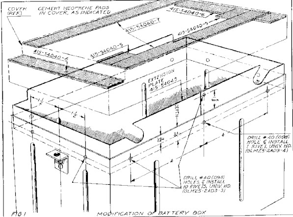
FIG 1
MODIFICATION OF BATTERY BOX
Service Memorandum No.44
SUBJECT : Electrical System Care and Maintenance of
This Memorandum is prepared to provide instruction on the care and proper maintenance of the Ercoupe electrical system, the installation
of which was covered in Service Memorandum No. 23. The proper maintenance of the electrical system is very important because its
malfunctioning can cause considerable structural damage. This Memorandum affects Ercoupe Serial Nos. 113 and subsequent. The
system should be checked within the next 60 days and at each 100 hour inspection thereafter.
1. Battery: (Reading R-24-7) (415-54044-20)
Reference-Storage Battery Technical Service Manual, distributed by Reading Batteries, Inc., Reading , Penna.
a. Check battery externally for loose terminals, bad cable connections, cracked case, cracks in top sealing compound, damaged
filler hole and vent plug.
b. Check charge of battery with hydrometer. (Readings taken at standard temperature of 80°F.) A fully charged battery
hydrometer reading is 1.275 to 1.300. If the reading is below 1.225, the battery should be bench recharged. Instructions for
the bench recharging will be found on the side of the battery case. If there is more than 25 points of specific gravity difference
between any cells, this is an indication that the battery is probably on the verge of failure.
c. Check electrolyte level in battery. (This must be done at 25 hour intervals or 30 days whichever occurs sooner.) Batteries both
with and without horizontal level plates have been used in Ercoupes. The electrolyte level in batteries having a horizontal level
plate (with a single hole in each cell) shall be no higher than flush with the plate. The electrolyte level in batteries having
horizontal plates should not be more than 1/4" above separators. Too high an electrolyte level may result in battery acid
overflowing or spilling. Capillary action of acid in vent tube, motion in rough air, or boiling of electrolyte due to overcharging,
will cause spilling of acid in batteries with too high an electrolyte level. An electrolyte level allowed to drop below the
separators may result in the following: plates and separators damaged due to to sulphation caused by exposure to air,
sulphuric acid becomes too concentrated causing damage to both separators and plates, and low battery output.
2. Battery Box Assembly: (415-54035). Leaking of battery acid from the
battery box assembly after spilling from battery will cause corrosion
of structural members around the battery box and deterioration of the
baggage compartment. A modification is being prepared to improve the
battery box assembly. The Bulletin on this modification will be
issued as soon as prepared, to facilitate field modification of the
battery box.
a. Check Battery Box for leakage, loose attachment to support, chipped acid proof paint, excessive corrosion, bent or loose
brackets, or loose deteriorated drain tube.
b. Check length of battery box drain tube as per instructions in Service Bulletin No. 8. (At least 1/2" extension below skin.)
c. Check battery box cover (415-54040) for chipped acid proof paint, excessive corrosion, or damaged wing bolts (415-54037),
bumper pads and elastic grommets (415-54040-2).
d. Check for new decal (415-54062) with battery maintenance instructions in lieu of one with instructions for weight and balance
only. (See Bulletin No. 22, part A).
3. Voltage Regulator: (Delco-Remy No. 1118-259) (415-53016-15).
Reference-Operators Manual for Delco-Remy Aircraft Electrical Equipment published by the Delco-Remy Division, General Motors
Corp., Anderson, Indiana (Supplied with all new Ercoupes since August 1946).
a. Check operation of generator and voltage regulator by running engine and observing ammeter readings. See Service
Memorandum No. 23 for proper readings and if faulty, refer regulator to authorized Delco-Remy Repair Station.
4. Miscellaneous Electrical Equipment:
a. Check remaining electrical equipment for proper operation, electrical wiring for proper taping of connectors and terminals.
Continuity of tests should be made on any doubtful wiring and worn wires should be replaced. Inspect 30 amp. fuse in the
generator circuit. Check switch and circuit breaker in navigation light circuit. A schematic electrical circuit diagram is included
with Memorandum No. 23.
5. Baggage Compartment:
a. The baggage compartment shall be inspected each time electrolyte level is checked for deterioration that may occur from
spilled battery acid. Damaged areas bay be mended by hand or machine sewn patches.
6. Airplane Structure:
a. The aluminum alloy structure, especially adjacent to and aft of the battery box, shall be carefully examined for corrosion due to
spilled acid. When corrosion is discovered it is of utmost importance that immediate steps be taken to neutralize active acid
and salt crystals. This may be accomplished by washing the affected area with a saturated solution of Bicarbonate of Soda or
a solution of Ammonia water (1 part household Ammonia, 4 parts water). Neither of these solutions are dangerous to handle,
however, they must be diluted to an inactive state by thoroughly flushing with water followed by drying. When using either of
these solutions it is imperative that ferrous metals be immediately treated with a protective coating to prevent oxidizing
(rusting). The above should be followed immediately upon the discovery of any corrosion, to prevent further damage.
b. The determination of the extent of the damage to the base metal in the affected area will require complete removal of all the
products of corrosion (scale, loose metal flakes, powder and salt crystals). When removing the products of corrosion caution
must be taken to remove only enough of the base metal to obtain clean surface. Chemical treatments are definitely preferred
but polishing is permissible for small areas. Chromic acid solution or an Alcohol-Phosphoric Acid solution may be used for
chemical cleaning. It is imperative, however, that neither of these materials be allowed to come in contact with organic
materials or be permitted to penetrate between frayed surfaces on into blind openings. They are not especially dangerous to
personnel.
c. The Chromic Acid Solution consists of 5% Chromic Acid dissolved in tap water and heated to 120°F. to 140°F. The wash may
be applied with either a brush or a soft cloth. The solution should be allowed to remain on he corroded area for five to ten
minutes. Remove the solution by rinsing with hot water while scrubbing lightly with a bristle brush. The area cleaned may then
be polished with 180 mesh emery sand paper or abrasive cloth, or wet or dry sand paper using water solvent as lubricant.
d. The Alcoholic Phosphoric Acid solution consists of a mixture as follows:
Quantity
Material by Volume
Butyl Alcohol 40%
Isopropyl Alcohol 30%
Phosphoric Acid (85% solution) 10%
Water 20%
This solution is used in the manner described for chromic acid except that the solution should not be allowed to remain on the aluminum for
more than 1 to 2 minutes.
e. After the above operations the affected areas should be protected from normal deterioration by painting zinc chromate before
reassembly. Exterior surfaces may be given a coat of clear lacquer protection.
f. If at any time battery acid has spilled in control cables or bearings, they should be removed and replaced. We do not
recommend any neutralizing steps for the above.
g. Affected steel parts should be removed from the airplane. The oxidization and corrosion removed with 180 mesh emery
sandpaper, abrasive cloth or wet or dry sandpaper using water solvent as lubricant. Steel parts should then be coated with
zinc chromate primer and re-installed.
Return