Failure of a fuel pump pressure line, due to chafing on the nose cowl has resulted in a change in the routing
of the fuel pump lines. This change was effected at serial number 3643. Ercoupes up to and including serial
number 3642 having fuel pumps incorporating metal filter bowl and bearing the AC part number 1539076 on
the mounting flange, will be affected by this memorandum. The fuel pumps which use a glass filter bowl (AC
1523843 and AC 15339051) are not affected. It is recommended that this memorandum be complied with
at the next 100 hour check because there is a possibility of an eventual failure of this line if not modified.
Inspection at each 25 hour check for chafing should be made until modification is effected.
1. Preliminary Operations:
a. Remove the following general parts:
1. Engine Top and Side Cow1ing Assembly (415-40422 and 415-40090 L/R).
2. Propeller Spinner (415-40593 or 415-40594). See Memo. No. 28.
3. Propeller (415-40500-2).
4. Engine Nose Cowl (415-40451).
2. Removal of Right Front Engine Cooling Baffle and Fuel Pump:
a. Remove cooling baffle and fuel pump as follows:
1. Disconnect both fuel pump hoses after removing damps.
2. Remove cooling baffle after removing front pump mounting nut and washer.
3. Remove fuel pump after removing rear pump mounting nut and washer.
3. Disassembly and Reworking of Fuel Pump:
a. Disassemble and rework fuel pump as follows:
(Ref. Page 3, Fig. 2. )
1. Cut safety wire and remove the six screws joining upper and lower halves. There will be
considerable spring pressure when removing the last screw.
2. Check the condition of the diaphragm while pump is disassembled. All fuel pump parts
necessary for repair are available from the Continental Motors Corporation, and AC
Automotive Service Stations.
3. Rotate top of pump 120° clockwise (two screw holes from the original position).
4. Reassemble pump halves with the six original lockwashers and screws.
5. Safety screws with brass safety wire, American Steel & Wire Gage No. 18 (.041 dia.)
6. Replace pump inlet port fitting with AN842-4D elbow, using Parker Sealube (6PE) on
threads.
7. Replace pump outlet port fitting with 415-48101-40 elbow having 1/16" restriction, using
Parker Sealube (6PE) on threads.
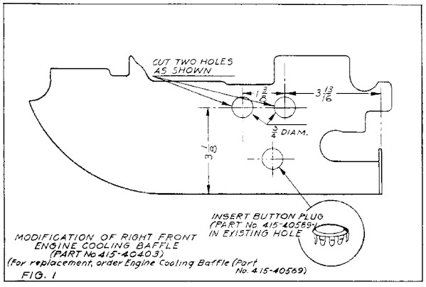
4. Reworking of Right Front Engine Cooling Baffle: (Ref. Page 3, Fig. 1)
a. Rework cooling baffle as follows:
1. Mark two holes in baffle as illustrated in Fig. 1 , Page 3.
2. Drill two 3/4" diameter holes at the above marks.
3. Install two elastic grommets (AN931-9-13) into the new holes.
4. Snap button plug (415-40589-1) into the extra unused hole.
5. Installation of Fuel Pump and Right Front Engine Cooling Baffle:
a. Install fuel pump and cooling baffle as follows:
1. Insert fuel pump hoses through respective holes, with grommets, in cooling baffle.
2. Install fuel pump being certain that wobble arm lays on top of cam-lobe inside of
crankcase.
3. Install nut and washer on rear pump mounting stud.
4. Place cooling baffle, and attach to front pump mounting stud with nut and washer.
5. Install Palnuts on both pump mounting studs after the nuts are tightened.
6. Shorten outlet hose (415-48201-3) as necessary to permit strain-free installation.
7. Install fuel pump hoses (415-48201-3) onto respective elbows.
8. Secure with two hose clamps (AN746-4) and safety clamps with brass safety wire,
American Steel & Wire gage No. 18 (.041 dia.)
6. Installation of General Parts:
a. Install the following general parts:
1. Engine Nose Cowl (415-40451).
2. Propeller. If crankshaft in engine is the flange type, torque propeller hub bolts (125175
inch/pounds), and then check track. The maximum track tolerance is 1/16". Safety hub
bolts with brass safety wire, American Steel & Wire gage No. 23 (.051 dia.)
3. Propeller Spinner (415-40923).
4. Engine top and side cowling assembly.
Fuel Pump Modification Service Kit No. 7 contains the following items:
Nomenclature Part Number Qty.
Elbow, Pipe thread and hose 45° 1/16" I.D. Restriction 415-48101-40 1
Elbow, Pipe thread and hose 90° (415-48101-41) AN842-4D 1
Plug, Button 415-40589-1 1
Grommet, Elastic (415-40400-55) AN931-9-13 2
The Kit may be purchased through Ercoupe Dealers at a price of $1.75 list.
